


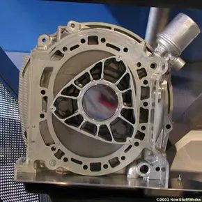
Piston engines are predictable. They suck in air, squeeze it, explode it, and blow out the exhaust. All inside the same metal tube. The piston moves up and down to handle each step. It’s a cycle of repetition. The rotary engine doesn’t do that. It’s an internal combustion engine, sure. But it abandons the piston entirely.
Think of a piston engine as a single room where four different chores happen sequentially. Intake. Compression. Combustion. Exhaust. One space. Four jobs. Now imagine a house where each room has a dedicated purpose. You walk from the kitchen to the living room to the bedroom to the bathroom. You never leave the house to do the chores. The rotary engine works like that house. Each stage of combustion gets its own dedicated chamber within the housing. The “piston” is a rotor. It spins. It moves continuously from one job to the next without ever reversing direction.
This design was originally conceived and developed by Dr. Felix Wankel. Hence the alternative name: Wankel engine or Wankel rotary engine. It’s distinct. It’s compact. It’s complex.
We are going to break down exactly how this triangular rotor spins inside an epitrochoid housing to create power. Let’s look at the basic principles that make a Wankel engine turn.
The Geometry of Power
The core of a Wankel engine is deceptively simple. You have two main moving parts. A triangular rotor. And a housing with curved, lobed walls. The housing isn’t circular. It looks like a circle that has been flattened and elongated at two points. Technically, it’s an epitrochoid shape. The rotor is a triangle with convex sides. It’s equilateral. Three equal sides. Three equal angles.
The rotor is mounted on an eccentric shaft. This is the output shaft. It doesn’t spin at the same center as the rotor moves. The rotor orbits while it spins. This eccentric motion creates the volume changes we need for combustion.
The Four Stages, Separated
In a four-stroke piston engine, one cylinder does all four strokes. The rotary engine splits them. The housing is divided into three separate chambers. As the rotor rotates, each chamber undergoes the four strokes simultaneously. But each chamber is in a different stage of the cycle.
- Intake : Air and fuel enter one chamber.
- Compression : The next chamber squeezes the mixture.
- Combustion : The third chamber ignites the fuel.
- Exhaust : A fourth phase expels the burned gases.
Because the rotor has three points, there are three working chambers. This means there is a power stroke every 120 degrees of rotor rotation. A piston engine needs two crankshaft revolutions (720 degrees) to complete one power stroke. The rotary engine delivers three power strokes in the same timeframe. That’s why they rev so high. That’s why they’re smooth.
Why It Matters
The Wankel engine offers a high power-to-weight ratio. Fewer moving parts. No camshafts. No valves. No timing belts. Just a rotor and a shaft. It’s lighter. Smaller. More compact than a
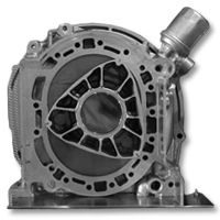

Why the Rotary Engine Doesn’t Make Sense (Until It Does)
You already know how a standard piston engine works. Air and fuel mix, they burn, and that pressure pushes a cylinder back and forth. Connecting rods and a crankshaft take that up-and-down chaos and turn it into the smooth rotation that spins your wheels. It is a well-worn formula.
The Wankel engine throws that out.
There are no pistons here. Instead, pressure is trapped inside a chamber defined by the housing and sealed off by one side of a triangular rotor. The rotor doesn’t just spin in a circle like a wheel. It orbits. Its path mimics a Spirograph drawing, keeping all three tips in constant contact with the outer wall.
This geometry creates three separate gas pockets. As the rotor moves, those pockets cycle through expansion and contraction. One pocket draws in the mixture. The next compresses it. The third ignites and expands to push the rotor around. The fourth expels the exhaust.
It is elegant. It is efficient. And it is notoriously difficult to build.
We are going to tear into the guts of this design next. But before we get our hands dirty with gears and seals, we need to look at where Mazda put this weird little heart in their newest MX-5.
The New MX-5 Rotary: A Case Study
Mazda didn’t just slap an old 13B into a modern chassis and hope for the best. They rebuilt the engine from the ground up. The result is the PVC (Power Valve Control) rotary engine found in the latest MX-5 RF.
This isn’t your father’s rotary. The old 13B suffered from poor fuel economy and high emissions. The new 11B-AP (or similar iterations depending on the market) addresses these issues directly.
Here is what is different under the hood:
- Direct Injection: Old rotors used port injection. The new design injects fuel directly into the combustion chamber. This allows for better atomization and precise control over the air-fuel ratio.
- Thermal Management: Cooling is harder in a rotary because the housing gets hot. Mazda added a more sophisticated cooling jacket and optimized the flow of coolant to keep the apex seals from melting.
- Reignited Ignition: The spark timing is more aggressive. By firing the plugs earlier in the cycle, they maximize the pressure curve before the exhaust ports open.
Why does this matter for the enthusiast? Because it proves the rotary isn’t dead. It just needed to grow up. The MX-5 with the rotary option isn’t just a novelty. It is a high-revving, smooth-as-silk alternative to the piston-four.
But looking at the specs is easy. Understanding why those apex seals wear out? That requires looking inside.


The Mazda RX-8 and the RENESIS Engine
Mazda didn’t just stumble into rotary engineering. They’ve been pushing this weird, efficient tech for decades. It started way back with the 1967 Cosmo Sport. Then came the trucks. The buses. Even the RX-7, which dropped in 1978 and became the king of rotary-powered cars. Sales in the US stopped after the 1995 model year. But the flame wasn’t out.
Enter the RX-8.
This wasn’t just a facelift. It was a fresh start built around a new heart. The RENESIS engine. It won International Engine of the Year in 2003. That’s a big deal. It’s naturally aspirated. Two rotors. No turbochargers screaming in the background. Just pure, spinning geometry. Output sits around 250 horsepower. Enough to make you look twice. Enough to keep the rotary dream alive while everyone else chased hybrid badges.
“Named International Engine of the Year 2003, this naturally aspirated two-rotor engine will produce about 250 horsepower.”
It’s clean. It’s tight. And it requires you to understand what makes a rotary tick before you can really appreciate why it matters.
The Parts of a Rotary Engine
Rotary engines don’t have pistons. They have triangles. That’s the first thing you have to unlearn. The core component is the rotor. It’s triangular. It spins inside an epitrochoid-shaped housing. The housing looks like a flattened oval with curved sides. The rotor’s tips maintain contact with the walls. Seals keep the compression chambers separate.
There are no valves. No camshafts. No crankshaft in the traditional sense. The offset center acts as a planet gear system. The rotor orbits while it spins. This creates four distinct phases in one rotation: intake, compression, combustion, exhaust. It’s a continuous cycle. Smooth. High-revving.
The apex seals are the weak point. They wear down over time. That’s why rotary engines need careful maintenance. The side seals help maintain compression between the rotor chambers. Without them, power bleeds off.
Oil is injected directly into the combustion chamber. It lubricates the seals. It also helps seal the gaps. This is why rotary engines burn oil. It’s not a defect. It’s a design feature.
The rotor housing is precision-machined. It’s not a simple cylinder. The shape is critical. It dictates the compression ratio. It dictates the efficiency. Mazda spent years perfecting this geometry. The RX-8’s RENESIS unit was the culmination of that work.
Why does this matter? Because it changes how you drive. There’s no vibration. No harsh shifts. Just a linear surge of power. The engine revs freely. It sings at high RPMs. It’s not for everyone. But for those who get it, it’s addictive.
The RX-8 wasn’t just a car. It was a statement. A reminder that there are still ways to make power that don’t involve hundreds of moving parts. The rotary engine is complex. It’s fragile. It’s brilliant. And it’s not going away anytime soon.
But understanding the parts is

The Rotor: Piston’s Weird Cousin
If you’re expecting a rotary engine to look like your average four-stroke, you’re in for a shock. The ignition and fuel delivery systems mimic standard piston engines, sure. But crack the casing, and the internal mechanics are entirely alien.
At the heart of this chaos is the rotor. It doesn’t push back and forth. It orbits.
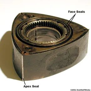
Each rotor features three convex faces. Think of them as individual pistons fused into a single triangular unit. These faces do the heavy lifting. Each one contains a recessed pocket. This design trick increases the engine’s displacement. More volume means more room for the air/fuel mixture to breathe.
Sealing is the hard part. Metal blades sit at the apex of each face. They scrape against the housing wall, forming a tight seal against the combustion chamber. Side seals—metal rings on either side of the rotor—handle the lateral pressure. Without them, you’d lose compression and power instantly.
Movement isn’t random. The rotor has internal gear teeth cut into its center. These mesh with a fixed gear inside the housing. That fixed gear dictates the rotor’s path. It forces the triangle into its unique epicyclic motion. One part spins. The whole assembly orbits.
It’s counterintuitive. It’s inefficient by traditional standards. And yet, it works.
“The rotor has a set of internal gear teeth cut into the center of one side. These teeth mate with a gear that is fixed to the housing.”
The geometry is rigid. You can’t change the path. The fixed gear locks the trajectory. The rotor follows.

The Engine Block
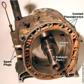
The outer casing isn’t a circle. It’s an epitrochoid. If you want to visualize the geometry, there are Java demos online that show exactly how the curve is derived. The math ensures one thing: the three corners of the rotor never lose contact with the inner wall. This contact creates three separate, sealed gas chambers.
Each section of the housing handles one phase of the power cycle.
- Intake
- Compression
- Combustion
- Exhaust
The ports for air and fuel sit directly in the housing. No valves. The exhaust port dumps straight into the exhaust system. The intake port connects directly to the throttle body.
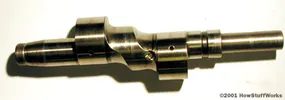

The secret to how a rotary engine spins lies in its output shaft. It isn’t a straight, simple cylinder. Instead, it features round lobes mounted eccentrically. That means they are offset from the shaft’s centerline. Each rotor slides over one of these lobes.
Think of it like a crankshaft in a traditional piston engine. As the rotor travels around the housing, it pushes against the lobe. Because that lobe is off-center, the force doesn’t just push outward. It creates torque. The shaft spins.
Simple physics. Effective engineering.
The Five-Layer Stack
Building a rotary engine assembly isn’t about bolting random parts together. It’s a layered process. Take the two-rotor Wankel engine we previously disassembled. It relies on five main layers. These layers are clamped together by a ring of long bolts.
Coolant doesn’t just sit in one place. It flows through passageways that surround almost every piece. Thermal management is baked into the structure itself.
The two end layers do heavy lifting. They house the seals and bearings for the output shaft. But they also seal the two housing sections where the rotors live.
Precision Surfaces Matter
The inside surfaces of these end pieces must be incredibly smooth. Why? Because the rotor seals rely on that finish to function. If the surface is rough, the seal fails. Power is lost. The engine dies.
Each end piece also contains an intake port. This is where the air-fuel mixture enters the system before hitting the rotating chambers. Without these ports, there is no combustion. Without combustion, there is no movement.
“The inside surfaces… help the seals on the rotor do their job.”
This precision is what separates a running rotary from a pile of scrap metal. One imperfection in those end caps, and the compression drops. The engine stalls.
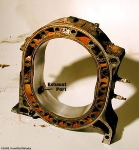

Look closer at the engine’s heart. The oval-shaped rotor housing sits just inside the outer shell. It’s not just a casing. It holds the exhaust ports. This is where the triangular rotor actually spins, trapped in that distinctive epitrochoid curve.
The rotor housing contains the exhaust ports and defines the combustion space for the triangular rotor.
The Centerpiece: Intake and Separation
At the core of the assembly lies the center piece. It’s a critical divider. This section houses two intake ports. One for each rotor chamber. Precision matters here. The outside surfaces of this center piece must be incredibly smooth. Why? Because it separates the two rotors. Friction is the enemy. Any roughness compromises the seal.
Sealing the Chamber
The geometry is tight. The center piece acts as a wall between the two working chambers. Each chamber has its own intake flow. The rotor rides against the housing wall. It also presses against the center piece. That’s why the finish on the center piece’s outer surfaces is so vital. It ensures efficient airflow and compression without leakage.
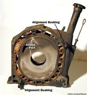

The geometry is what makes it work. Inside the triangular casing, a large internal gear sits in the center of the rotor. It orbits a smaller, fixed gear attached to the engine housing. This setup dictates the rotor’s path. The rotor also grinds against a large, circular lobe on the output shaft.
That interaction defines the engine’s unique motion. Here is how that motion creates horsepower.
The Mechanical Advantage of Offset Lobes
Rotary engines follow the four-stroke combustion cycle. Same as a piston engine. Different execution.
Watch the offset lobe on the output shaft. It spins three times for every single revolution of the rotor.
The rotor is the heart. It replaces the pistons. Mounted on that offset lobe, the rotor acts like a crank handle on a winch. The lobe is offset from the shaft’s centerline. This gives the rotor leverage. As the rotor orbits inside the housing, it pushes the lobe into tight circles.
Three output shaft rotations per one rotor revolution.
As the rotor moves, the three chambers it forms change volume. This creates a pumping action. Let’s break down the four strokes by looking at one face of the rotor.
Intake Port Exposure
The cycle begins when the rotor tip passes the intake port.
At that exact moment, the chamber’s volume is near minimum. The port is exposed. As the rotor moves past, the chamber expands. It sucks in the air-fuel mixture.
When the rotor’s peak clears the intake port, the chamber seals. Compression starts immediately.
Compression Phase
The rotor keeps moving. The chamber volume shrinks.
The air-fuel mixture gets squeezed. By the time the rotor’s face reaches the spark plugs, the volume is at its absolute minimum.
That is the trigger point. Combustion begins.
Combustion and Power
Most rotary engines use two spark plugs.
The combustion chamber is long. One plug would cause the flame front to spread too slowly. Two plugs ensure a faster, more complete burn.
Ignition spikes the pressure. The rotor moves.
The combustion gases expand, pushing the rotor in the direction that grows the chamber volume. This creates power. The process continues until the rotor’s peak passes the exhaust port.
Exhaust and Cycle Reset
Once the peak clears the exhaust port, high-pressure gases escape.
The rotor keeps moving. The chamber starts contracting. This forces out any remaining exhaust.
By the time the chamber volume hits minimum again, the rotor’s peak hits the intake port. The cycle resets.
The efficiency of this design is stark. Each of the three rotor faces works on a different part of the cycle simultaneously. One full rotor revolution yields three combustion strokes.
But here is the catch. The output shaft spins three times per rotor revolution. So, you get one combustion stroke for every output shaft revolution.
Why Fewer Parts Means Less Vibration
The mechanical reality of a Wankel engine is starkly different from the pistons you see in most road cars. A two-rotor setup has just three main moving components: the two triangular rotors and the eccentric output shaft. Compare that to a modest four-cylinder piston engine, which requires at least 40 moving parts. You are looking at pistons, connecting rods, camshafts, valves, springs, rockers, timing belts, gears, and a crankshaft.
Fewer parts usually means fewer things to break. That reliability is exactly why some aircraft manufacturers prefer rotary engines over traditional piston blocks.
The smoothness comes from the motion itself. In a rotary engine, every component spins continuously in one direction. There is no violent reversal of direction like the up-and-down stroke of a piston. Internal counterweights are phased to cancel out vibrations, creating an internal balance that piston engines struggle to match.
Power delivery is equally consistent. Each combustion event spans 90 degrees of the rotor’s rotation. Since the output shaft spins three times for every single turn of the rotor, that combustion event lasts for 270 degrees of the output shaft’s rotation. A single-rotor engine delivers power for three-quarters of every revolution.
Consider a single-cylinder piston engine. Combustion occurs during 180 degrees of a two-revolution cycle. That is only a quarter of each revolution of the crankshaft. The rotary engine provides a much longer window of power application.
The Speed and Efficiency Trade-offs
Because the rotors spin at one-third the speed of the output shaft, the main moving parts are under less stress. This slower movement contributes to the reliability mentioned earlier. It is not just theory; it is kinematic fact.
However, these engines are not without significant hurdles. Designing a rotary engine that meets strict U.S. emissions regulations is notoriously difficult. The long, thin shape of the combustion chamber is inefficient. It leads to poor thermodynamic efficiency and a lower compression ratio. The result is higher fuel consumption compared to a piston engine of similar output.
Manufacturing costs are also a barrier. Since the volume of production is far lower than for piston engines, the per-unit cost remains high. You are paying for rarity and complexity.
Common Questions About Wankel Motors
How does a rotary engine work?
It separates the four strokes of an internal combustion engine—intake, compression, combustion, exhaust—into four distinct chambers within the housing. The rotor moves between these chambers, expanding and contracting the gas mixture to drive the output shaft.
Why are rotary engines considered problematic?
The disadvantages are primarily economic and regulatory. Meeting emissions standards is harder due to the combustion chamber geometry. Manufacturing costs are higher because production volumes are low. Fuel economy suffers because the engine’s thermodynamic efficiency is reduced by its shape and low compression ratio.
Is a rotary engine better than a piston engine?
It depends on what you value. They offer superior smoothness by eliminating the violent direction changes of pistons. They have fewer moving parts, which can increase reliability. They operate with slower-moving internal components. But they often burn more fuel and cost more to build. There is no perfect balance, only trade-offs.
The debate continues because the rotary engine offers a unique mechanical solution that still carries significant engineering baggage. You get smoothness and simplicity in a package that fights against modern efficiency demands. It is a compromise, but one that some enthusiasts are willing to make.


